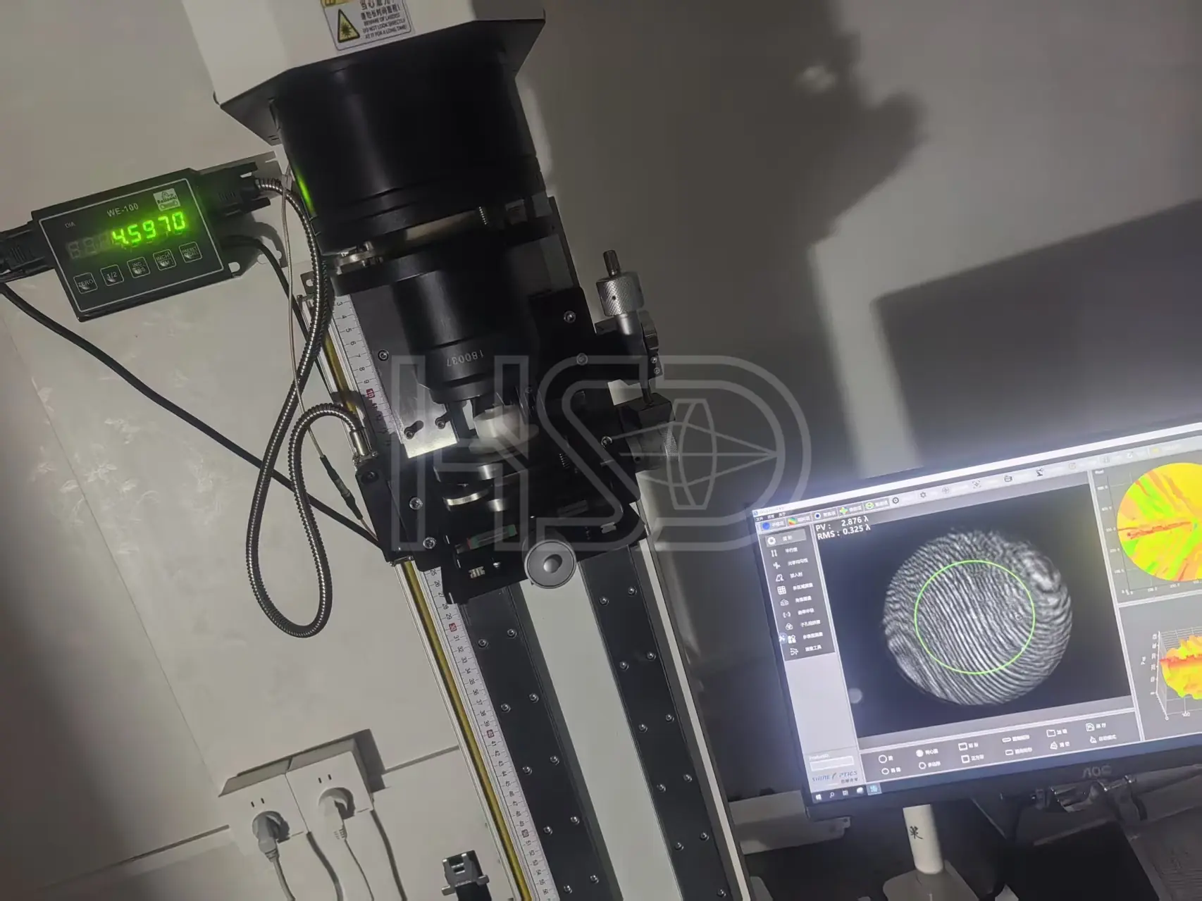
Surface Figure
Surface form tested by interferometry — PV/RMS values from the actual measurement.
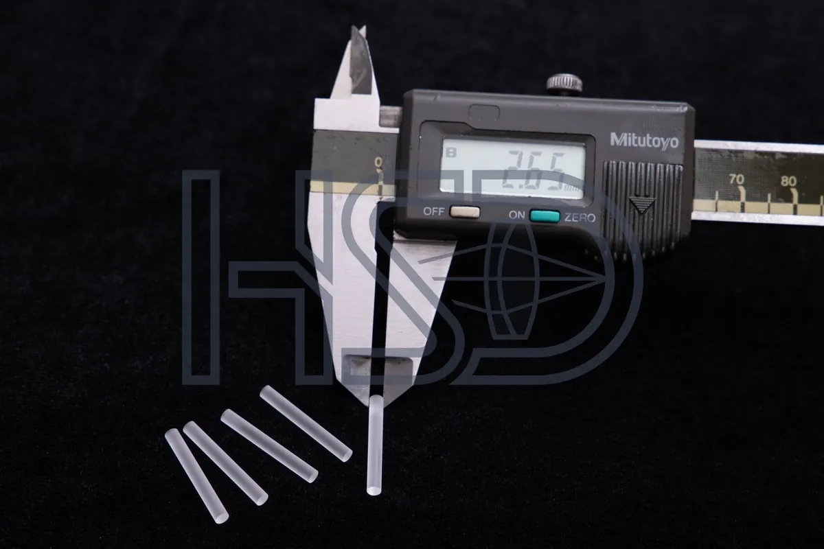
1 · A rod that doesn't fit stops the line. In a slim tube there is no room to compensate: a relay rod 0.02 mm over seats hard, 0.02 mm under rattles. Fit is decided at the supplier's bench, not yours.
How HSD avoids it: diameter is held to −0.02/−0.04 mm and measured on the batch COA before parts leave the factory.
2 · Centration errors stack even in a short chain. A small centration error on one rod softens the image in the assembled scope — no visible defect on the part itself.
How HSD avoids it: centration is verified on a per-batch sampling plan per ISO 10110-6, with measured values on the COA.
3 · The “manufacturer” may be a reseller. Drawings forwarded to several small shops; when yield drops, nobody owns the root cause.
How HSD avoids it: we are the factory — your drawing is reviewed by our own engineers, not forwarded to a third party.
4 · Drift shows up at your assembly, not at inspection. Batch-to-batch shifts pass incoming checks and surface as rework at final build.
How HSD avoids it: every batch COA carries measured values so drift is visible at incoming inspection.
A slim-tube build works when the rods arrive as a matched set: same diameter logic, same length logic, same centration method.
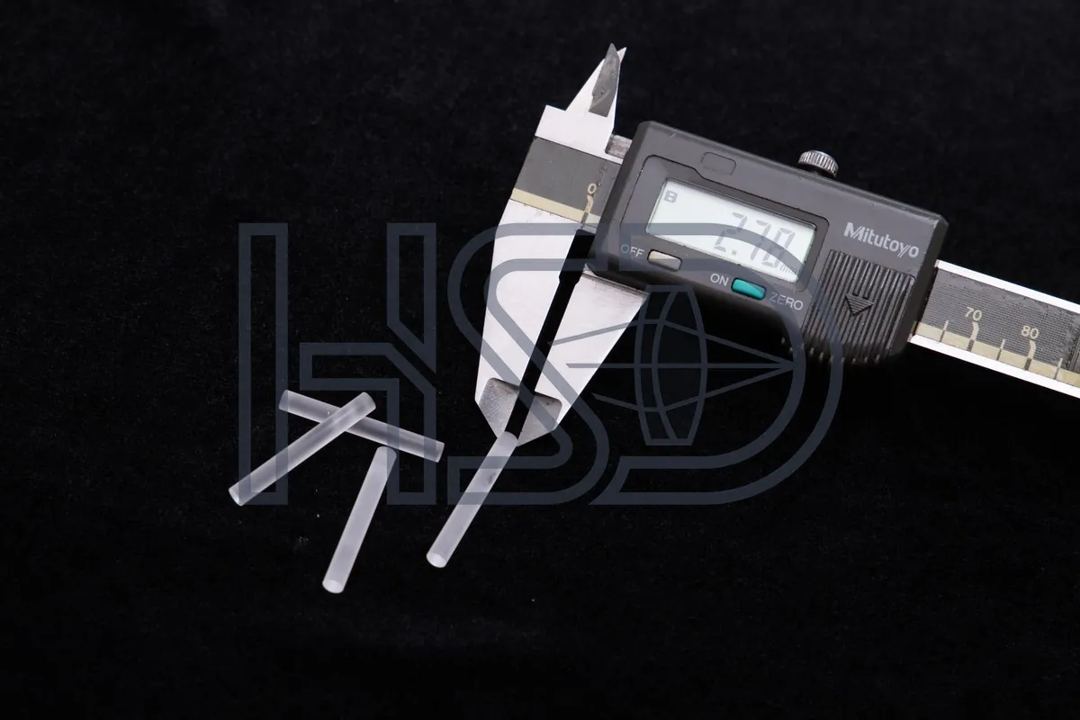
Relay rods, rear rod lenses, slim relay rods and uncoated rod lens blanks — all make-to-print. Photos below are HSD production shots, labeled by diameter; final specifications per your drawing.
Other make-to-print sizes: slim relay rods (Φ1.19–1.96) · rear rod lenses (Φ6 class) · eyepiece relay rods · uncoated rod lens blanks — send your drawing and our engineers check every dimension, tolerance and assembly relation, one by one.
| Item | Specification |
|---|---|
| Rod lens diameter range | Φ1.19–8.0 mm (cystoscope relay rods typically Φ2.8–4.0) |
| Diameter tolerance | −0.02 / −0.04 mm (fit) |
| Centration | ≤3′, tighter per drawing |
| Surface quality | 40/20 · MIL-PRF-13830B / ISO 10110-7 5/40-20 |
| Edge chipping | ≤0.05 mm, per drawing · ISO 10110-7 E 0.05 |
| Coating | BBAR 400–700 nm, R<0.5% (per drawing) |
| Glass | Per drawing: JGS1 / H-ZF / H-LAK / H-K9L / N-SK15; material certificates with each batch |
| Length tolerance | Per drawing |
For cystoscope rods, the COA shows measured diameter, length and centration per batch, not a within-spec line.
Send the cystoscope rod drawing and engineering will confirm the compact fit and quote within 24 hours.
Send Your Drawing → Email [email protected]Application context
Cystoscope relays are compact, typically Φ2.8–4.0 mm, where tube space is limited. This page focuses on make-to-print cystoscope relay rods with centration measured per batch.
Check on the drawing: compact diameter, relay length and centration datum; edge treatment is confirmed with the drawing.
The compact diameter and tight relay spacing. We confirm the drawing first, then hold the same tolerance and COA process as the rest of the range.
Inspection & Metrology
Every batch is verified with interferometry, centration measurement and surface inspection. You get the actual measured values, not a “within spec” checkbox.
Surface form tested by interferometry — PV/RMS values from the actual measurement.
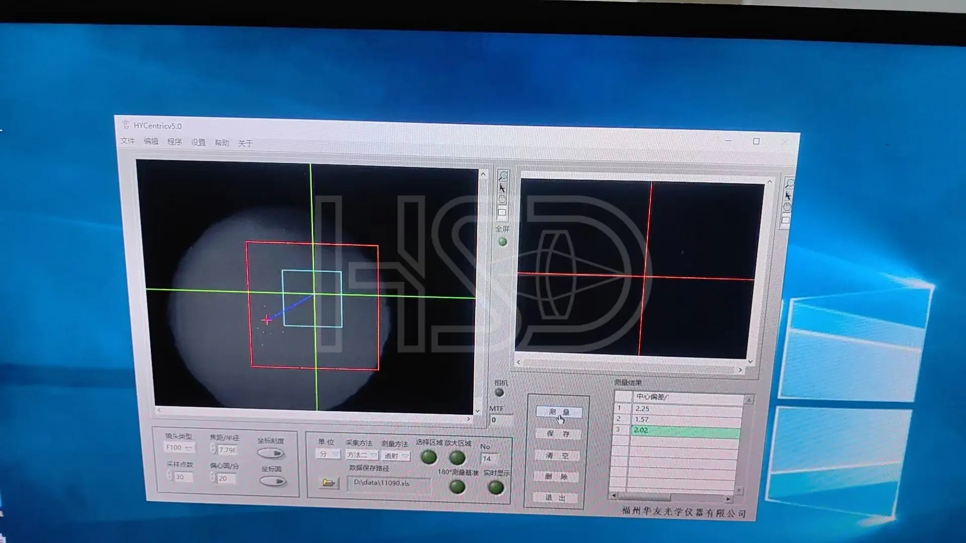
Centration checked on the centration station, typically ≤3′. The reading shown is from a real part — 2.02′.
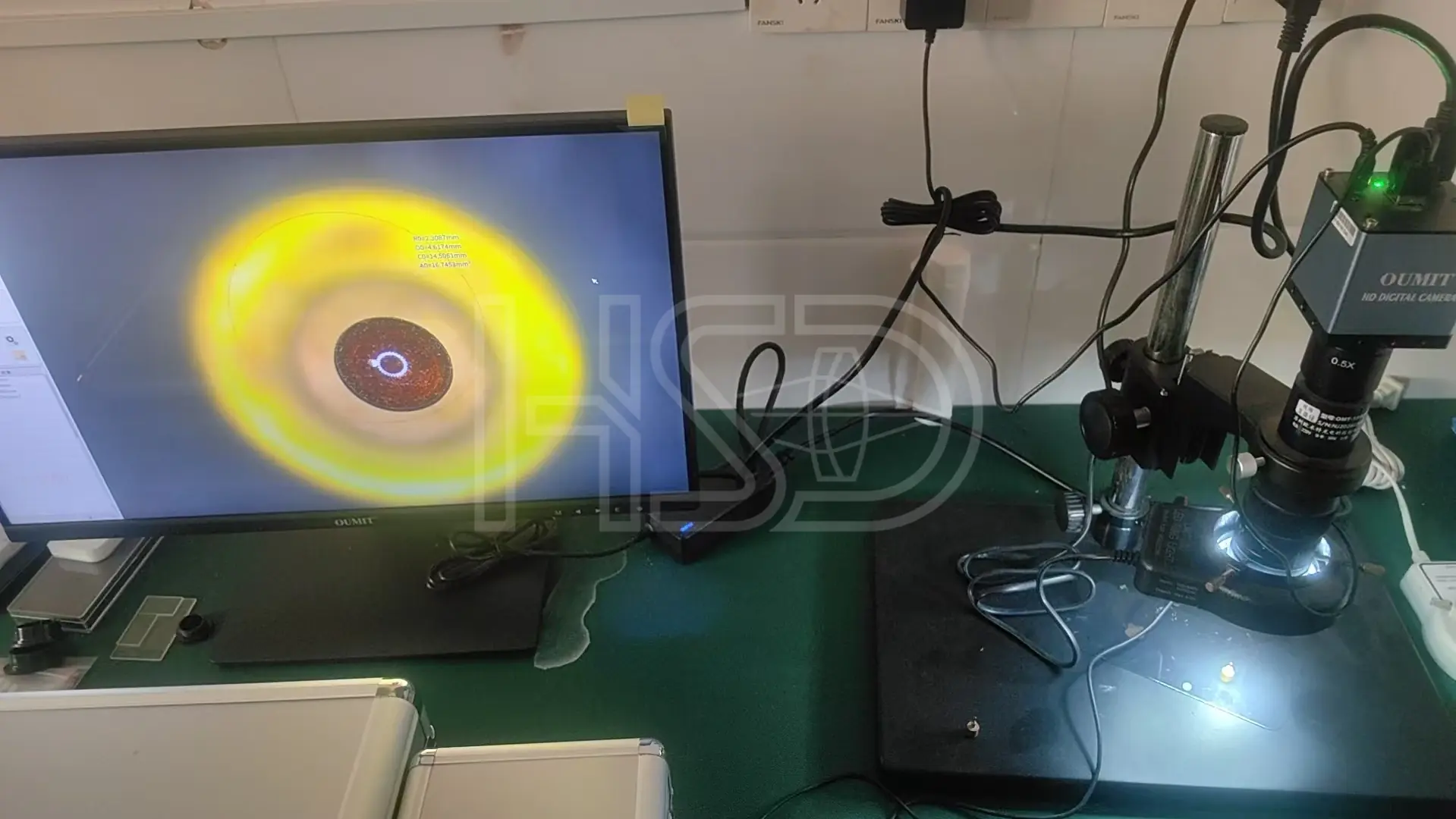
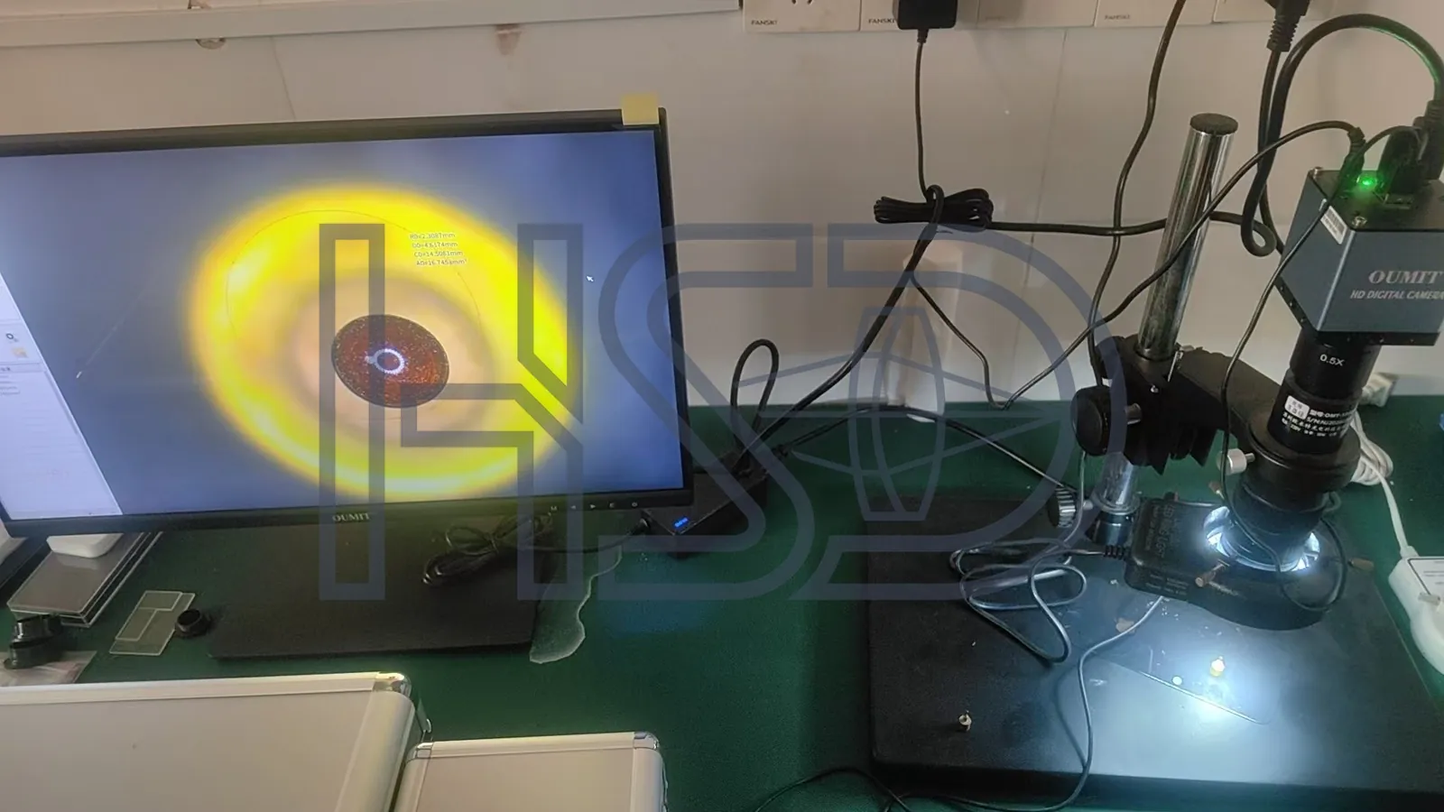
Surface and edge quality inspected under a video microscope — scratch/dig per MIL-PRF-13830B.
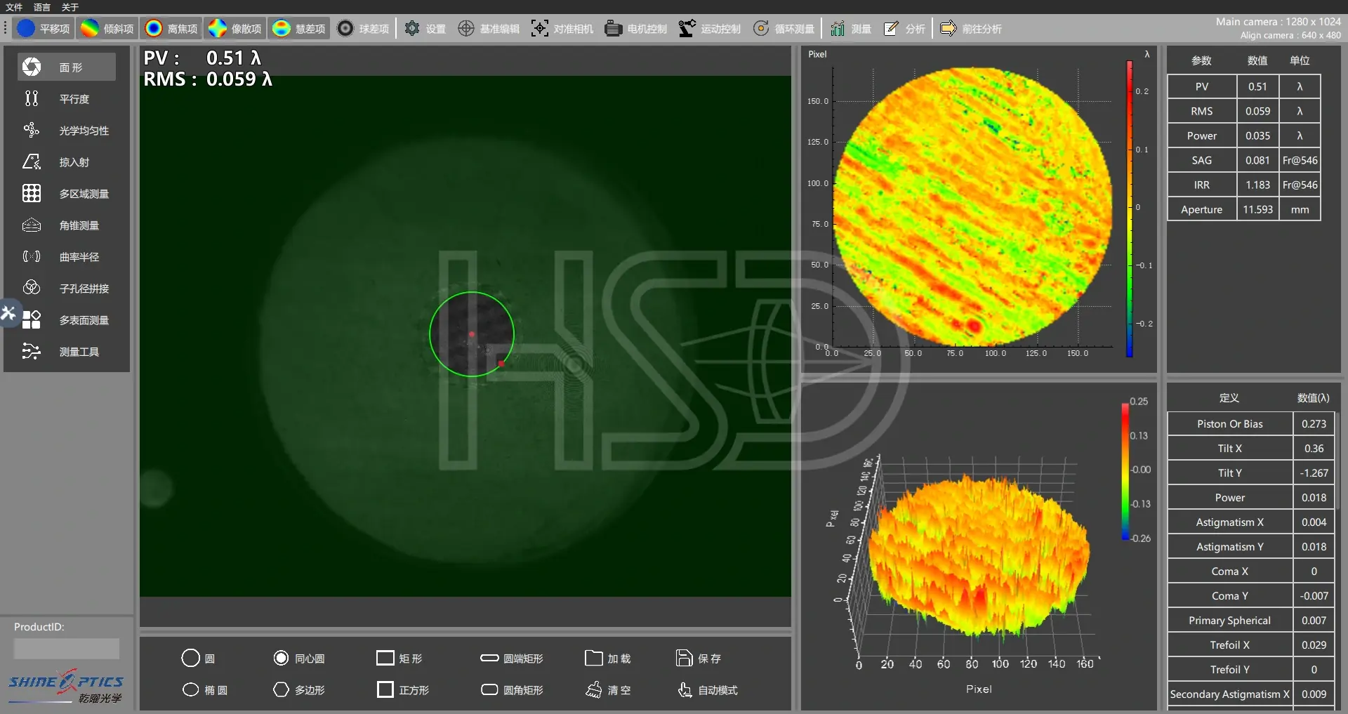
A passing surface from a production run: PV 0.51λ, RMS 0.059λ. Rejects never leave the workshop.
Measured COA per batch — ask for a sample COA with your quote. · Learn how to read a surface map →
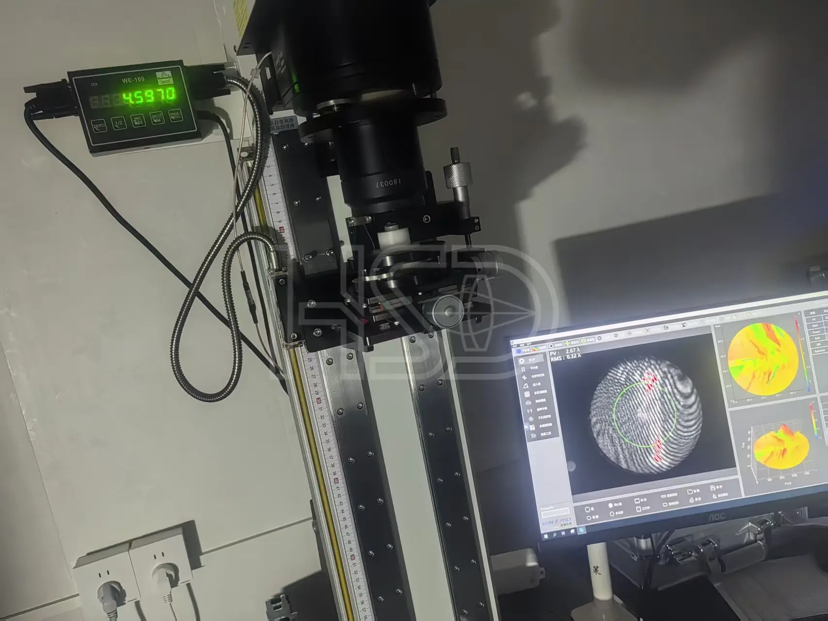
Multiple scratches caught in inspection — PV 2.67λ; the batch was stopped before shipping.
Real measurement, kept on file. Your COA gets the same kind of data.
Watch rod lens grinding, polishing, centration measurement and final inspection in real time. All information shared during the tour is confidential — your NDA is welcome.
Schedule a Live Video Tour